Section 4: General Radiography
Introduction
This chapter provides information on the requirements and procedures for quality assurance testing of general radiographic x-ray machines.
Mandatory HARP Tests
Patient Entrance Exposure
Half-value Layer
Collimation
Recommended Technical Tests
Exposure Reproducibility
Kilovoltage Accuracy
mA/mAs Linearity
mA Meter Accuracy
Timer Accuracy
Leakage Radiation
Equipment List
The following equipment is required to test basic radiographic functions of x-ray machines.
- Dosemeter
- Measuring Tape
- Kilovoltage meter
- Collimation test tool
- Digital timer
- Aluminium filters (4 x lmm and 2 x 0.5mm)
- Masking tape
General Setup<
Many of the tests performed to evaluate a radiographic x-ray machine are set up in the same manner. Tests which use a similar setup are: PEE, half-value layer, mA or mAs linearity, timer accuracy and exposure reproducibility.
Equipment
- Radiation dosemeter
- Tape measure
Procedure
- Place the dosemeter in its stand on a flat surface (usually the x-ray table).
- Position the chamber of the dosemeter probe 23 cm above the table top.
- Position the x-ray tube over the chamber at the target-film distance used for a majority of radiographic views. This distance is most commonly 102 cm (40") (target to film distance).
- Collimate the x-ray field to 10 cm by 10 cm at the table.
Note: The following tests are presented in a logical sequence. This order expedites the testing process and minimizes the number of exposures which must be taken.
Exposure Reproducibility
Standard
Section 13 (2) of the HARP Regulation states:
"Every diagnostic x-ray machine shall be so constructed that,
- over the normal range of use of the machine for any given combination of the x-ray tube potential (in kilovolts peak), tube current (in milliamperes), exposure time (in seconds) or for selected radiation exposure to the image receptor (in milliroentgens),
- the estimated coefficient of variation of any ten consecutive radiation exposure measurements taken at the same source-to-detector distance within a time period of one hour is no greater than O. 08, and
- each of the ten radiation exposures referred to in subclause (i) is within 20 per cent of the mean value of the ten measurements."
Procedure
- Set up the test equipment according to the directions provided in the general setup. (See preceding page for procedure.)
- Select an exposure technique which provides a measured exposure of 100 mR or higher. The following techniques are recommended: 80 kVp, 200 mA, 0. 1 - 0.2 seconds or an Abdomen technique for a 23 cm patient.(Comment: The generator must be able to hold reproducibility under any normal use setting. Use 80kV, lowest used mAs on manual setting.)
- Make three exposures and record the output of each of the exposures.1 Generally, for routine HARP testing done every six months, reproducibility testing can be limited to three exposures. This should be enough information to reveal whether there is a reproducibility problem. If a problem is suspected then take ten exposures and calculate the coefficient of variation.(Webmaster Notes 20021207: Reproducibility varies because of tolerences on electromechanical components, voltage variations on set points, different resistances across relay points, line voltage variations, etc. Measure 5 static, and 5 dynamic to ensure that the equipment can deliver consistant output as requested. Dynamic means change all the settings, and reset back to previous values.)
- Calculate the mean of the outputs. Determine whether each of the measurements is within 20 per cent of the mean.
1Allow sufficient time between exposures for the tube to cool. Refer to each x-ray tube's heat rating chart.
Evaluate as follows:
Reproducibility must meet the HARP regulation's standard described above. If not, the x-ray unit must not be used until it is serviced and retested.
To save time on calculating you may wish to use the following rule of thumb. If each of the output measurements is within 20 per cent of the mean, the exposure reproducibility is probably acceptable. If one or more of the measurements are not within 20 per cent of the mean, exposure reproducibility is probably not acceptable and the coefficient of variation must be calculated.
The coefficient of variation is evaluated as follows.
(1) Coefficient of Variation Formula
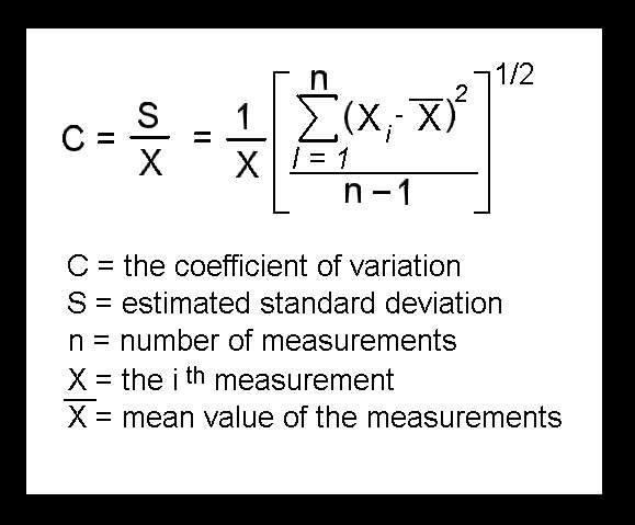
- Some number, n, of measurements is made at a constant technique.
- Their average is calculated (X with bar over it).
- The difference between each measurement and the average value is obtained.
- Each of these differences is squared.
- These square values are totalled.
- This sum is then divided by the (n-l) to obtain the expected variance.
- The square root of this value is obtained (Standard deviation (S)).
- This is divided by the average (x) of the original measurements. Step 2 above.
See next page for an example.
|
| Sample Measurements and Calculations |
| Exposure # (n value) |
Value (Xi) (mR) |
Difference from Mean |
Square of Differences |
| 1 |
237 |
(3.5) |
12.25 |
| 2 |
250 |
9.5 |
90.25 |
| 3 |
242 |
1.5 |
2.25 |
| 4 |
240 |
(0.5) |
0.25 |
| 5 |
244 |
3.5 |
12.25 |
| 6 |
248 |
7.5 |
56.25 |
| 7 |
230 |
(10.5) |
110.25 |
| 8 |
235 |
(5.5) |
30.25 |
| 9 |
241 |
0.5 |
0.25 |
| 10 |
238 |
(2.5) |
6.25 |
| Total |
|
|
320.5 |
| |
|
|
|
| Explanations |
| 1. 10 measurements were taken. | |
| 2. Mean: (X with bar over it) is calculated | (2405/10)=240.5 |
| 3. The difference between each measurement (n) and the Mean (average) is taken. Eg. for Measurement #1: | Difference from mean = 327 - 240.5 = -3.5
Repeat this step for each measurement (Column 3). |
| 4. The differences are squared. | Eg. Measurement #1 (3.5)x(3.5) = 12.25
Repeat this step for each measurement (Column 4) |
| 5. The squares are totalled. | 320.5 |
6. The sum is now divided by (n-1),
Expected variance: | 320.5/(10-1) = 35.6 |
| The square root of this value is now obtained. | =5.96657 |
| 8. This is now divided by the average(mean). (See step 2.) | =240.5 |
| Coefficient of variation 5.96657/240.5 = 0.0248 | This is less than 0.08 therefore the reproducibility of this unit is acceptable. |
mA Linearity
Standard
Section 13 (4) of the HARP Regulation states:
- "Where a diagnostic x-ray machine is constructed so that the tube current (in milliamperes) has a range of preset values and both it and the exposure time (in seconds) can be selected individually, the average ratios of exposure (in milliroentgens) to the product of tube current and exposure time, obtained at any two adjacent tube current settings for any fixed indicated value of x-ray tube potential (in kilovolts) over the normal range of use of the machine, shall not differ by more than O. 10 times their sum or
where x1 and x2 are the average mR/mAs (milliroentgens divided by milliampere-seconds) values obtained at the two selected settings of mA (milliamperes)."
Equipment
- Radiation dosemeter
- Digital X-ray Timer (optional)2
- Measuring tape
Procedure
- Set up the test equipment according to the directions provided in the general setup. (See General Radiography - Section 4)
- If possible, place both the digital x-ray timer and dosemeter chamber in the x-ray field. If not possible, then place the ionization dosemeter chamber only. Ensure that the meters are completely contained in the x-ray field. Set the timer to pulses (for a single phase generator) or seconds (for a three-phase generator).
- Select 80 kVp, 0.2 seconds for a single phase generator or 80 kVp, 0. 1 seconds for a three-phase generator.
- Select the lowest mA station within the normal range of use.
- Take an exposure and record the output (millir6entgens) and number of pulses or time (seconds).
- Select the next higher mA station adjacent to the first mA station. Ensure that the Kilovoltage is maintained at 80 kVp throughout the test.
- Take an exposure and record the output (milliroentgens) and the number of pulses or the time (seconds).
- Repeat steps 6 and 7 until all adjacent mA stations in the normal range of use have been checked.
- Calculate the mR/mAs for each station checked.
2The timer may be used to record times for timer test as other tests are being performed. Testing will proceed quicker with less stress on the x-ray tube.
Evaluate as follows:
If linearity does not meet this standard, the unit must be serviced and retested. Note, timer function and Kilovoltage accuracy should be checked as possible sources to this problem.
Calculate whether the mA stations are linear to each other by using the following formula:
(2) mA Linearity Formula
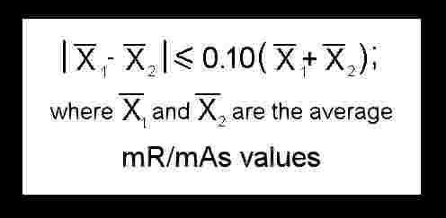
X is mR/mAs
Example
The x-ray machine is set at 80 kVp and 0. 1 seconds. The output measured at 50 mA was 80 mR, at 100 mA the output was 165 mR.
| mA Setting | Output | mR/mAs |
| 50 | 80 | 16.0 |
| 100 | 165 | 16.5 |
Calculation:
(16.5 - 16.0) 0.10(16.5 + 16.0)
0.5 0.10(32.5)
0.5 3.25
0.5 is less than 3.25. Therefore, mA linearity is acceptable between 50 and 100 mA stations.
|
mAs Linearity
Standard
Section 13 (5) of the HARP Regulation states:
- "Where a diagnostic x-ray machine is constructed so that the exposure selection can be made only as the tube current exposure time product (in milliampere-seconds) or where the milliampere value is continuously variable, the average ratios of exposure (in millirOentgens) to the product of tube current and exposure time, obtained at any two selections of milliampere-second differing by at least a factor of two, for any fixed indicated value of x-ray tube potential (in kilovolts) within the range of normal operation of the machine, shall not differ by more than O. 10 times their sum or
where x1 and x2 are the average mR/mAs (milliroentgens divided by milliampere-seconds) values obtained at the two selected settings of (milliampere-seconds)."
Equipment
- Radiation dosemeter
- Digital X-ray Timer (optional)3
- Measuring tape
Procedure
The procedure for testing mAs linearity is virtually identical to testing mA linearity. Instead of setting mA stations, mAs selections are chosen. Starting at the lowest mAs setting used, then double each subsequent setting up to the maximum mAs used.
Follow the procedure as stated for mA Linearity, noting the changes indicated above.
3
The timer may be used to record times for timer test as other tests are being performed. Testing will proceed quicker with less stress on the x-ray tube.
mA Meter Accuracy
Procedure
- Select 60 kVp, the mA station most commonly used and approximately one second.
- While observing the mA meter, make an exposure and record the value registered by the mA meter.
- Select another mA station used and repeat step 2.
Evaluate as follows:
The values registered on the mA meter must be within 50 per cent of the selected mA. Failure to meet this standard will require servicing of the mA meter.
|
Patient Entrance Exposures
Standard
Section 8 (11) of the HARP Regulation states:
"Every medical radiation protection officer, every chiropractic radiation protection officer, and every chiropodic radiation protection officer shall ensure that at the facility where the officer acts, the entrance exposure of that part of a patient set out in Column 1 of Table 6 of a thickness set out opposite thereto in Column 2 of Table 6 that is a distance from the x-ray source set out opposite thereto in Column 3 of Table 6 does not exceed the exposure set out opposite thereto in Column 4 of Table 6."
In January 2001, new limits for mammographic procedures were set. These are based on Mean Glandular Dose, as opposed to skin entrance exposures. The new limit is 3 mGy. |
| TABLE 6: Radiographic Skin Entrance Exposures |
| Column 1 | Column 2 | Column 3 | Column 4 |
| Projection | Patient Thickness* | Proposed limits (mR) | Maximum Entrance Exposure**(mR) |
| 1. | Abdomen AP | 23 cm | 350 | 450 mR |
| 2. | Cervical Spine AP | 13 cm | 70 | 120 mR |
| 3. | Chest PA | 23 cm | 20 | 20 mR |
| 4. | Foot (Dorso-Plantar) Direct film | 8 cm | n/a | 200 mR |
| 5. | Full Spine | 23 cm | 250 | 250 mR |
| 6. | Intravenous Pyelogram | 23 cm | 350 | 500 mR |
| 7. | Lumbar spine AP | 23 cm | 300 | 500 mR |
| 8. | Lumbar spine Lateral | 32 cm | 1100 | 2,000 mR |
| 9.(a) | Mammogram | 4 cm *** | see above | 3 mGy
(Revised Dec. 2001) |
| 10. | Skull Lateral | 15 cm | 80 | 170 mR |
| 11. | Thoracic Spine AP | 23 cm | 200 | 400 mR |
R.R.O. 1990, Reg. 543, Table 6
* standard for test purposes
** exposures expressed as exposure in air without backscatter
*** compressed breast
|
Patient Entrance Exposures - Continued
Equipment
- Dosemeter
- Masking Tape
- Calculator
Procedure
- Set up the test equipment according to the directions provided in the general setup. (See General Radiography - Section 4).
- Set the exposure factors for the projection which is being assessed per the facility' s technique charts. (To select appropriate patient thickness see Column 2 of Table 6).
- Make an exposure and record the measurement.
- Repeat steps 2 and 3 using the exposure factors for each of the other projections normally performed in the x-ray room.4 If certain projections are not performed in the room being tested, there is no need to measure the PEE for these projections.
- Calculate PEE using the Inverse Square Law, for those PEEs which use a different target-to-skin distance (eg. chest) or a different patient thickness (eg. lateral skull).
Evaluate as follows:
- All PEEs test results must be below the Ontario limits (Column 4 of Table 6).
- Any PEE test results above the Ontario limit must be reduced immediately.
- Any PEE test results near the Ontario limit should be investigated with a view toward reduction.
- Any PEE test results at or above the Ontario Proposed limits (Column 3 of Table 6) should be attempted to be reduced to the proposed limit.
4 There is no need to adjust the position of the tube to measure projections of direct patient thickness or different target-to-film distance.
Example
Inverse Square Law
I(2) the new exposure (x)
I(1) the known(measured) exposure
D(1) the target meter distance used at the measured exposure squared
D(2) the distance at the new exposure squared
The following is an example of how to calculate the PEE for a patient measuring 32 cm lateral lumbar spine. Using the Lateral Lumbar Spine technique factors the measured exposure was 500 mR at 23 cm from the table top.
Therefore;
D(1)the target to dosemeter distance squared is (97-23)2= 5476
D(2)the distance from the target to the patient skin for patient measuring 32 cm is (97-32)2=4225
I(1)the dose measured at D(1) is 500 mR
I(2)the new exposure (x)
By using the inverse square law the PEE for a lateral lumbar spine is 648 mR:
(3) Inverse Square Law
|
Half-Value Layer
Section 9(3)(b) of the HARP Regulation states:
(b) filters that;
- are located in the exit port of the x-ray tube housing or beam limiting device or both,
- intercept the entire useful beam, and
- at a measured potential set out in Column 1 of Table 8 with a thickness of aluminum set out opposite thereto in Column 2 of Table 8, reduce the exposure at least by half."
|
| TABLE 8: |
| ITEM | Column 1 | Column 2 |
| Measured Potential
(kilovolts peak) | Minimum
Half-Value Layer
(millimetres of aluminum) |
| 1. | 30 | 0.3 | |
| 2. | 40 | 0.4 | |
| 3. | 49 | 0.5 | |
| 4. | 50 | 1.2 | |
| 5. | 60 | 1.3 | |
| 6. | 70 | 1.5 | |
| 7. | 71 | 2.1 | |
| 8. | 80 | 2.3 | |
| 9. | 90 | 2.5 | |
| 10. | 100 | 2.7 | |
| 11. | 110 | 3.0 | |
| 12. | 120 | 3.2 | |
| 13. | 130 | 3.5 | |
| 14. | 140 | 3.8 | |
| 15. | 150 | 4.1 | |
Equipment - Half-Value Layer Measurement
- Dosemeter
- Alaminam sheets (Type 1100 alloy -- at least 2 sheets 0.5 mm and 4 sheets 1.0 mm thickness)
- Masking tape
Procedure
- Set up the test equipment according to the directions provided in the general setup. (See General Radiography - Section 4).
- Select an exposure technique which provides an output of approximately 100 mR or higher at a measured kVp station. In keeping with the exposure reproducibility test, the following techniques are suggested: 80 kVp, 200 mA, 0. 1 - 0.2 seconds.
- Make an exposure and record the output. This is the zero reading.
- Tape 2.5 mm of aluminam to the face of the collimator.
- Make an exposure and record the output.
- Compare the second measurement to the first:
Half-value Has Not Been Reached:
If the addition of aluminum filters (step 4) has not reduced the original exposure (zero reading) by 1/2 or less, then carry on by adding more aluminum filters. Repeat this by adjusting the amount of filters until the added amount of filtration reduces the original output to 1/2 of its original value.
Half-value Has Been Reached:
If the added amount of filtration (step 4) has reduced the original output to 1/2 or more then you have reached or passed the Half-value Point. Remove 1 mm of filtration from step 4 and repeat the exposure.
Remove all added sheets of alaminam and repeat the exposure to ensure that the radiation output has remained constant throughout the test and that the x-ray tube has not been moved.
Calculate the half-value layer (mathematically or by plotting on semi-log graph paper) and record the value.
Compare the measured half-value layer for measured kVp, to the values in Table 8 of the HARP Regulation.
Evaluate as follows:
- If the measured half-value layer meets or exceeds the minimum requirement as stated in table 8, the x-ray machine has sufficient filtration.
- If the measured half-value layer is less than the minimum requirement stated in Table 8, the machine must be serviced. Additional filtration must be added to the x-ray tube and the balf-value layer test repeated to confirm that sufficient filtration is in place.
|
Timer Tests
Standard
Section 11 (1) of the HARP Regulation states:
"Every diagnostic x-ray machine and every fiuoroscopic x-ray machine shall be so constructed that the timing device on the machine terminates an irradiation on completion of:
- a preset time interval,
- a preset product of current and time; or
- a preset number of pulses,
Except where the x-ray machine is equipped with an automatic exposure control device."
Section 11 (3) of the HARP Regulation states:
"Every timing device on a diagnostic x-ray machine and fiuoroscopic x-ray machine shah be so constructed that it,
- resets automatically to its original position or to ZERO on termination of an irradiation,' and
- prevents an irradiation from occurring at the ZERO or OFF position."
Section 13 (2 c-d) of the HARP Regulation states:
"Every diagnostic x-ray machine shall be so constructed that,
- (c)the timer on the x-ray machine may be set to control irradiations as short as 1/30 second or five milliampere-seconds, whichever is greater;
- (d) at each setting over the normal range of use, the timer on the x-ray machine is accurate to within +/- 10 per cent."
Equipment
- Digital X-ray Timer Meter
Test for:
- Exposure at zero or at off position
- Timer accuracy
- Deadman
- Automatic reset
- Minimum exposure
Procedure
- Set up the test equipment according to the directions provided in the general setup. (See General Radiography - Section 4).
- Place the digital x-ray timer on the x-ray table.
- Collimate the x-ray beam to ensure that the timer's chamber is within the x-ray field and centred.
- Select 80 kVp.
Testing for Exposure At Zero
Ensure the timer is inoperative at Zero or Off position (if applicable).
Make an exposure with the time set at the Zero or Off position of the timer (if applicable).
The x-ray machine must not produce an exposure when set at the Zero or Off position. If an exposure is measured, the machine must not be used again until the problem is corrected.
Testing for Timer Accuracy
Test for accuracy by measuring the timer output for each time setting within the normal range of use. Expose and record the measured time in pulses for a single phase generator, in seconds for a three-phase generator. This can be limited to testing only a few timing stations and if these are correct then assume that the remainder are accurate. Measured time must be accurate to within +/-10 per cent of that selected.
Testing Deadman
Ensure that the timer has a deadman feature. That is a switch that requires continuous pressure by the operator to produce x-rays, except where the x-ray machine is equipped with a programable repetitive switch for special procedure such as a serial changer, CT etc.
After making one full exposure at the maximum time setting (within the normal range of use), we recommend 1.0 second, take a second exposure at 1.0 second, however this time make this one a partial exposure, that is release the exposure switch before it has reached 1.0 second (deadman). Ensure that the second exposure time measured is much less than the first.
Note: this test is difficult to do, therefore, we suggest that it be done with not less than a one second exposure time.
If the deadman function does not work, the unit must not be used again until the problem is corrected.
Testing for Timer Resets or Zeros on Completion of Exposure
The timer must automatically reset itself to its original position or to zero after any exposure. If the machine does not reset or go to zero, it must not be used again until the problem is corrected.
Testing for Minimum Exposure Time
The x-ray machine must be capable of producing exposure on time as low as a 1/30 second or 5 mAs, whichever is greater.
Select the shortest exposure time and ensure that it is within the standard listed above.
Evaluate as follows:
If any of the following do not meet standards, the x-ray machine must not be used until such time that is has been serviced and test(s) repeated to confirm proper functions.
Minimum Exposure Time
- The x-ray machine must be able to be set at 1/30 second or 5 mAs.
Timer inoperative at Zero or Off Position
- The x-ray machine must not produce an exposure when the timer is set at the zero or off position. If an exposure is measured, the machine must be immediately taken off-line and serviced.
Timer Accuracy
- Measured time must be accurate to within �1/30 second or � 10 per cent.
Timer Resets or Returns to
Zero on Completion of
Exposure
- The timer must automatically reset or remm to zero after an incomplete or complete exposure. If the machine does not reset or return to zero, it must be immediately taken off-line and serviced.
Reproducibility
- Ensure timer is reproducible within a coefficient of variation of 0.08
Deadman
- Radiation stops whenever the operator releases the exposure switch before the selected time has been reached.
Note: the above requirements also apply to the exposure control in the AEC mode. |
Collimation Test
Standard
Section 15 (1)(2)(3) of the HARP Regulation states:
- Every general-purpose radiographic x-ray machine and every mobile radiographic x-ray machine sha11 be equipped with an x-ray beam limiting device that,
- provides for stepless adjustment of the size of the x-ray field;
- provides for a minimum field size that does not exceed five centimetres by five centimetres at a target-to-image receptor distance of lO0 centimetres; and
- ensure that at each position, the x-ray field is aligned with the image receptor in such a manner that the x-ray field is always confined within the boundaries of the image receptor.
- An x-ray beam limiting device referred to in subsection (1) shall,
- be equipped with an adjustable light beam diaphragm or other device that defines visually the outline of the x-ray field when the axis of the x-ray beam is perpendicular to the plane of the image; or
- allow the operator to adjust the dimensions of the x-ray field at the image receptor to a size smaller than the dimensions of the image receptor.
- An adjustable light beam diaphragm or other device that defines visually the outline of the x-ray field shall be so constructed that,
- misalignment of the visually defined field with respect to the x-ray field along either the length or width of the x-ray field does not exceed 2 per cent of the target-to-image receptor distance; and
- the size of the x-ray~eld in the plane of the image receptor is indicated at selected distances that are accurate to within 3 per cent of the target-to-image receptor distance.
Section 16 of the HARP Regulation states:
Every general-purpose radiographic x-ray machine that is used with only one size of image receptor at a fixed target-to-image receptor distance shall be equipped with a device to ensure that,
- the centre of the x-ray field is aligned with the centre of the image receptor to within 2 per cent of the target-to-image receptor distance; and
- the x-ray field in the plane of the image receptor does not extend beyond any edge of the image receptor.
Light Field to X-ray Field Congruency
There are several methods to do this test. Choose one of the following methods.
Light Field to X-ray Field Congruency (Method 1 )
Equipment
- Measuring tape
- One loaded film cassette
- Nine pennies
Procedure
- Place a loaded cassette on the table top.
- Select a target-to-film distance of 100 cm.
- Centre the light field to the centre of the cassette.
- Collimate such that the light field is 2.5 cm to 3.0 cm (1" to 1.5") from each edge of the cassette.
- Position two pennies at the centre of each margin of the light field so that one entire penny is inside the light field and one penny is outside the light field. Ensure that each of the pennies touches the margin.
- Place the ninth penny in the middle of the lower right quadrant of the light field to act as an orientation marker.
- Expose the cassette using 60kV and approximately 2 mAs.
- Process the film.
Evaluate as follows:
Measure the displacement of the x-ray field with respect to the light field. Remember, the x-ray field should be between each pair of pennies. If the sum of the displacement (length/width) is greater than 2 cm (2% of 100 cm) of the length or width away from the light field margin, the x-ray machine must be serviced.
Note: this test can be performed with the cassette/film in the bucky if applicable.
Light Field to X-ray Field Congruency - Method 2
Equipment
- Measuring Tape
- One Loaded Cassette
- Collimation Test Tool
Procedure
- Place a loaded cassette on the table top.
- Place the collimator test tool on top of the loaded cassette, centred to the cassette.
- Select a target-to-film distance of 100 cm.
- Adjust the collimator shutters so that the edges of the light field lineup with the rectangular outline printed on the collimator tool. Note the position of the orientation marker.
- Expose the cassette using 60 kVp with approximately 2 mAs.
- Process the film.
Evaluate as follows:
Measure the displacement of the x-ray field with respect to the light field. If the sum of the displacement (length/width) is greater than 2 cm (2% of 100 cm) of the length or width away from the light margin, the x-ray machine must be serviced.
Note: this test can be performed with the cassette/film in the bucky if applicable.
Collimator Scale Congruency
Select one of the following methods.
X-ray Field to Collimator Scale Congruency - Method 1
Equipment
- Measuring Tape
- Loaded Cassette
- One Penny
Procedure
- Place a loaded cassette on the table top. We suggest a 25 x 30 cm (10 x 12 inch) cassette.
- Place a penny in the lower right quadrant of the cassette. Position the x-ray tube 100 cm above the cassette, centred to it.
- Select a field size of 10 by 10 cm using the collimator scale selector for 100 cm.
- Expose the cassette using 60 kVp with approximately 2 mAs.
- Process the film.
Evaluate as follows:
Measure the length and width of the blackened area on the film. This should measure close to 10 x 10 cm or at least within 7 to 13 cm, allowing for 3% of distance used. A variation in measurement by greater than 3% (3 cm at 100cm) will require servicing of the collimator scales.
X-ray Field to Collimator Scale Congruency - Method 2
Equipment
Procedure
- This test must be done after the light field to x-ray field congruency test (method 1).
- If the results of the above test show that the light field and x-ray field are congruent, collimator scale accuracy may be determined by measuring the length and width of the light field and comparing this to the scate selector. A variation in measurement by greater than 3% of the target film distance used will require servicing of the collimator scales.
Minimum X-ray Field Size
(Select one of the following methods)
Minimum X-ray Field Size - Method 1
Equipment
- Loaded Cassette
- Measuring Tape
Procedure
- Place a loaded cassette on the table top.
- Position the x-ray tube 100 cm above the cassette, centred to it. Close the collimators to their minimum field size.
- Expose the cassette using 60 kVp, 2 mAs.
Evaluate as follows:
Measure the dimensions of the blackened area of the x-ray film. If the measurement is larger than 5 by 5 cm, the collimator must be serviced.
Minimum X-ray Field Size - Method 2
Equipment
Procedure
- This test must be performed after the light field to x-ray field congruency test (either method).
- If the results of the above test show that the light field and x-ray field are congruent, the minimum field size requirement may be determined visually. Position the x-ray tube 1O0 cm above the table top.
- Close the collimator blades to their minimum field size.
- Activate the light field and measure the light field size at the table.
Evaluate as follows:
If the light field measurement is larger than 5 by 5 cm, the collimator must be serviced.
Maximum X-ray Field Size
For Fixed Aperture
If several sizes of film are used with a unit that uses a fixed aperture to collimate, then several appropriate size apertures are required to ensure that there is always a means to limit the x-ray field size to within the film size used.
Equipment
Testing X-ray field size with a fixed aperture
- Measuring tape
- Loaded cassette
Procedure
- Measure the target-image receptor distance normally used.
- Position a loaded cassette as close as possible to the aperture opening of the collimator.
- Measure the target to film distance.
- Expose the cassette using 60 kVp with approximately 2 mAs.
- Process the film.
- Measure the width and length of the blackened area on the film.
The x-ray field size at the image receptor can be determined mathematically using the ratio of similar triangles. Measure the distance from the focal spot to radiograph used in the test. Measure the distance to film that is normally used by the facility. Measure the width and length on the exposed film used for the test.
(4) X-Ray Field size d = (a x c)/b
- a -- size of exposed area on the radiograph (calculate for the width first, then repeat for length)
- b -- distance focal spot to film
- c -- distance focal spot to image receptor as used by facility (cassette holder).
- d -- size of radiation field at image receptor.
Evaluate as follows:
The size of the calculated x-ray field must be within the size of film used. |
Kilovoltage Accuracy
Standard
Section 13 (2b) of the HARP Regulation states:
"Every diagnostic x-ray machine shall be so constructed that,
(b) for any selected setting of the peak x-ray tube potential over the normal range of use of the machine, the average peak kilovoltage corresponds to the selected value to within +/- 8 per cent."
Equipment
- Digital kilovoltage meter
Procedure
- Select radiographic mode of operation on the kilovoltage meter.
- Select single phase, three-phase or constant potential on the kilovoltage meter (if applicable). The selection depends upon the type of generator being tested.
- Position the kilovoltage meter on the x-ray table top so that the detectors are centred to and flooded by the x-ray beam.
- Set the x-ray machine to 60 kVp, 200 mA and 0.2 seconds.
- Make an exposure and record the kilovoltage measured.
- Repeat for 80, 100 and 125 kVp (if these values fall within the normal range of use).
Evaluate as follows:
Kilovoltage must be accurate to within +/- 8 per cent. If any of the measured values fall outside of this range, the x-ray machine must be recalibrated. In addition, kVp should also be assessed at other milliamperage stations commonly used.
|
Leakage Radiation
Standard
Section 14 of the HARP Regulation states:
- The leakage radiation measured at a distance of one metre in any direction from an x-ray source shall not exceed 100 milliroentgens in one hour under any conditions.
- The leakage radiation measurements referred to in subsection (1) shall be averaged over an area of l00 square centimetres with no linear dimension greater than twenty centimetres. "
Equipment
- Survey meter
- 3.0 mm thickness of lead
Procedure
This test should be performed only when there is noticeable damage to the tube housing. Tube rating charts must be followed when performing this test.
- Close the collimator blade completely.
- Place a 3.0 mm thick piece of lead on a flat surface (such of the x-ray table).
- Position the collimator face in close contact with the lead.
- Select the maximum exposure that is obtainable within tube ratings.
- Select rate mode on the survey meter and position the instrument, one meter from the focal spot.
- Expose and record leakage radiation.
- Measurements at 5 positions are necessary for leakage assessment:
- 1 metre anteriorly from the focal spot.
- 1 metre posteriorly from the focal spot.
- 1 metre laterally from each side of the focal spot.
- 1 metre above the focal spot.
Evaluate as follows;
If any of the measurements are greater than 100 mR/Hr, using the maximum output at one meter, the tube assembly must be serviced.
|
Bone Densitometer
All bone densitometers must:
- Be registered with the Ministry of Health.
- Have radiation shielding plans approved by the Ministry of Health.
- Have Acceptance Tests performed on them.
- Follow the manufacturer's guidelines for daily/weekly regular QC testing.
End of Section 4: If General Radiography unit has AEC exposure control, see Section 5: Automatic Exposure Control.
|

