Section 10: Dental X-Ray Machines
Summary of Required Quality Assurance Tests for Dental Facilities
This chapter provides information on the requirements and procedures for quality assurance testing of dental x-ray machines. Included in this chapter are the following equipment types: intra-oral, panoramic, cephalometric and machines modified to perform tempero-mandibular images.
Mandatory HARP Tests
Patient Entrance
Exposure Half-value Layer
Collimation
Other Technical Tests
Kilovoltage Accuracy
Output Reproducibility
Timer Linearity
Exposure Switch Function
|
All dental X-ray units must be registered with the Ministry of Health - X-Ray Inspection Service. This includes the location of the X-ray unit and the name and business address of the owner.
Before the installation of any new or used dental X-ray unit or the relocation of an existing dental x-ray unit, plan approval must be obtained from the Director of X-ray Safety at the Ministry of Health. After the installation or relocation, acceptance testing must be done on the x-ray unit and submitted to the X-ray Inspection Service within sixty days.
Only a dentist licensed by the Royal College of Dental Surgeons of Ontario (RCDS) can order x-rays.
The following persons may take x-rays of patients:
- Dentist licensed to practise in Ontario.
- Dental Hygienist licensed to practise in Ontario.
- Dental Assistant who has successfully completed a course in radiation safety that has been approved by the HARP Commission.
- The Radiation Protection Officer (RPO) is responsible for the safe use of radiation. In a solo practice, the dentist is the RPO. In a group practice or a clinic, one specific dentist must be designated as the RPO.
The duties of the RPO are:
- To ensure that only qualified persons operate the dental X-ray unit.
- To ensure that the X-ray equipment is maintained in a safe working order.
- To notify the Ministry of Health - X-ray Inspection Service of any new installation or relocation of existing dental X-ray units and ensure appropriate shielding is put in place.
- To ensure appropriate acceptance tests are carried out on any new installations or relocations.
- To conduct yearly quality assurance tests on the x-ray machines and daily processing tests and maintain records of such tests.
- To ensure entrance exposure dose to patients does not exceed specified limits. For posterior bitewing films, these limits are listed in Chart 1.
- To advise the director of X-ray safety of any accident involving over-exposure to a patient.
- To promote any means to reduce patient exposure without sacrificing image quality.
Chart 1
|
50 kVp |
maximum exposure of 550 mR |
|
60 kVp |
maximum exposure of 420 mR |
|
70 kVp |
maximum exposure of 360 mR |
|
80 kVp |
maximum exposure of 280 mR |
|
90 kVp |
maximum exposure of 220 mR |
The following tests must be performed at the indicated frequencies and records kept of the results.
|
Test |
Frequency |
|
Photographic quality control |
Every operational day |
|
PEE dose |
Every 12 months |
|
Collimation |
Every 12 months |
|
Half-value layer |
Every 12 months |
Photographic Quality Control
Required Tests
Monitoring of the developer temperature each operational day and ensuring it is within the range specified by the manufacturer and/or supplier of processing solutions.
Logging the replacement of processing solutions and cleaning of the processor.
Recommended Tests
Recording the number of films processed each day.
Logging the checking and replenishment of processing solutions each day.
Exposure of a step wedge to assess continuity in contrast and density
Film repeat analyses.
The purpose of the test is to ensure that the processing aspect is acceptable and not producing poor quality film rendering unnecessary repeat exposures to patients.
Another method to monitor photographic quality control is to make a test object, radiograph it, process the film and check it for image quality. A simple test object can be made in about three minutes. See Dental X-ray Machines - Section 10 for Dental Stepwedge Analysis and the end of this section on how to construct your own stepwedge, or test object tool.
Automatic Processors
Equipment
Non-mercury thermometer (alcohol or metal is recommended, in order to prevent contamination of the processor or chemicals by mercury in the event of thermometer breakage).
Procedure
Check the temperature of the developer daily prior to processing the first radiograph.
Check the solutions level daily.
Expose a stepwedge daily (optional) and assess contrast and density.
Logging the replacement of processing solutions and cleaning of the processor.
Recording the number of films processed each day.
Logging the checking and replenishment of processing solutions each day.
Dental Step Wedge Analysis
Equipment
Step Wedge (instructions for assembly provided at the end of this section)
Periapical Films
Procedure
Place a periapical film on a counter top or other convenient surface and position the step wedge on top of the film.
Centre the cone of the x-ray tube head to the step wedge and position it 1/2 cm. above the stepwedge.
Expose the film using normal bitewing exposure factors.
Develop this film. The resultant film should show a degradation of densities. If not you could be overexposing the film. Keep this film by the processor as it becomes your reference film "standard" to which all other films taken in the course of the week will be compared to until new chemistry is put in the developer.
Repeat the first three steps on eight to ten additional unexposed periapical films for future testing. Do not develop these films at this time. During the course of the week, each day develop one of the exposed film and compare this to film developed the first day in step 4 and note any changes. If the film densities do not match continue to step 6. Continue this process until new chemistry is in place at which time the whole process is started up again.
If you suspect the quality of your film is deteriorating, try to determine what is causing the problem and rectify before developing any films taken of patients.
Note:
A visible difference in corresponding step images indicates an output difference of approximately +/- 20 percent. It is possible that the patient may be receiving an overexposure.
Manual Processing
The time/temperature method of processing films must be followed, according to the chemical manufacturer's directions. Sight development must NEVER be done as it promotes the use of higher radiation exposure to patients and often results in poor quality radiographs.
17
17 Proper photographic chemical tanks (opaque) should be used.
The tanks should have a lid to cover the chemicals to minimize oxidation.
Solutions should be changed at regular intervals as recommended by the manufacturer.
Solutions should be topped up or replenished according to manufacturer's instructions.
Equipment
Non-mercury Thermometer
Minute Timer
Procedure
Post the chemical or film manufacturer's time/temperature development chart near the processing tanks so that it is readily available for reference.
Check the temperature immediately before processing the film.
The film is then developed for the time specified for that temperature on the development chart. An alarm timer is necessary for accuracy.
After development, wash and fix according to the chart.
Technical Quality Assurance Tests
In-House Procedure
If a dentist wishes to do his/her own testing on site, a dosemeter is required. Several makes and models of dosemeters are available which are suitable for this purpose. If convenient, for cost effectiveness, several dental facilities can share a dosemeter.
Patient Entrance Exposures and half-value layer may be measured by dental staff using the test methodology described on the following pages.
18
18 PEE limits have not been determined at this time for panoramic or cephalometric dental radiography. Due to the narrow x-ray beam used in panoramic machines, the PEE cannot be accurately measured using routinely available instrumentation. However, cephalometric exposure can be measured and generally should not exceed 50 mR per film.
Outside Assistance
There are two methods used by outside agencies:
- Most quality assurance companies will visit the dental office, take measurements with test instruments and provide the dentist with a written report. This method offers the advantage that additional tests, above and beyond the minimal HARP requirements will be performed. In addition, these companies may be able to assist the dentist in improving radiographic film quality.
- In the second method, the dentist receives a sealed packet containing a special film. The packet is exposed using normal posterior bitewing exposure factors and then returned to the agency for analysis. A report is mailed back to the dentist, indicating any deficiencies in half-value layer, PEEs or collimation which may require attention. This method meets the minimum requirements of the HARP Act and is reliant upon the dentist following directions explicitly.
Intra-Oral
Patient Entrance Exposure
Standard
Section 8 (12) of the HARP Regulation states:
"Every dental radiation protection officer shall ensure that at the facility where the officer acts, the entrance exposure of that part of a patient set out in Column 1 of Table 7 at the measured potential set out opposite thereto in Column 2 of Table 7 does not exceed the exposure set out opposite thereto in Column 3 of Table 7."
Equipment
Radiation dosemeter
Procedure
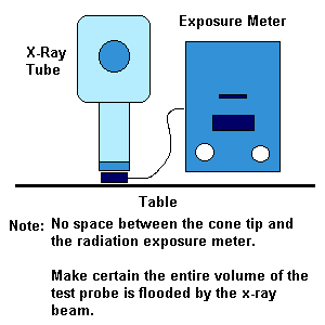
FIGURE 10-1 Intra-Oral PEE Setup
- Place the dosemeter on a flat surface.
- Position the tube so that the end of the cone tip is within 1 cm from the dosemeter detector and the primary beam is centered to the detector. See Figure 10 - 1.
- Select the exposure factors set on the intraoral x-ray machine or as used clinically for a posterior bitewing examination.
- Make three exposures. As long as the unit is reproducible, take the average to obtain the PEE.
- Compare the PEE with those specified in Table 10 - 1. Make certain that the measured PEE is compared with the appropriate kVp used. 19
19 The exposures listed above refer to "D" type film. If you are using "E" type film, thc patient exposure measurement should be one-half of that listed in the table.
- If the measured PEE is higher than that allowed by the table, the cause of the high exposure should be investigated and corrective action taken.
Table 10-1
|
ITEM |
COLUMN 1 |
COLUMN 2 |
COLUMN 3 |
|
1 |
Posterior Bitewings |
50 |
550 |
|
2 |
Posterior Bitewings |
60 |
475 |
|
3 |
Posterior Bitewings |
70 |
360 |
|
4 |
Posterior Bitewings |
80 |
280 |
|
5 |
Posterior Bitewings |
90 |
220 |
Collimation and Beam Alignment
Standard
For intra-oral x-ray machines, Section 21 (1) of the HARP Regulation state:
"Every dental x-ray machine shall be so equipped with a beam limiting device that limits the size of the useful beam to a maximum linear dimension of seven centimetres at the end of the localizing cone or device."
A simple test is used to assess collimation and determine the alignment of the x-ray beam.
Equipment
Five dental films (periapical or bitewing) or one extra-oral film.
Procedure
Method 1 -- Using Dental Films
Figure 10-2 Placement of Films
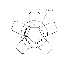
- Punch a single hole in one of the five films with a pin. Punch two holes in the second film. Continue with the remainder of the films increasing the number of holes punched by one for each film. There should be five holes in the fifth film.
- Place the five films on the counter in a star-shaped pattern, with the corners touching.
- Centre the cone to the films, with the cone touching the film. (See Figure 10 - 2.)
- Note the position of each film (by number of holes) relative to the front, back and sides of the tube head.
- Expose the films using approximately 0.2 - 0.25 seconds.
- Process the films.
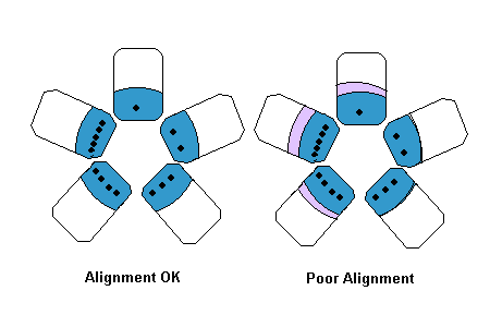
- Evaluate the films by measuring the diameter of the area exposed and by looking for any misalignment of the x-ray beam or collimation disc. Misalignment of the collimation disc will often show an extra halfmoon area of primary exposure outside the main exposure area. (See Figure 10 - 3.)
Method 2 -- Using Extra-Oral Film
Figure 10-3 Misalignment of Collimator Disc
- Secure the film on a flat surface and position the cone touching the film.
- Place markers on the film at the edge of the cone. Different markers may be used to identify different rooms.
- Expose the film using bitewing factors.
- Proceed to the next intra-oral x-ray machine to be tested and position the tube over an unexposed area of the film, as done with the first machine.
- Continue testing additional machines as in steps 1 to 3, using unexposed areas of the film. Three exposures can be made on a panoramic film, and four exposures can be made on a 8 x 10 inch cephalometric film.
- Develop film and evaluate the resultant radiograph. Exposed areas should be circular and no more that 7 cm. in diameter. If exposed areas are oval, greater than 7 cm. diameter, or if any extraneous radiation is seen, the service representative should be contacted to correct the collimation.
Half-value Layer
Standard
According to Section 9 (3b) (iii) of the HARP Regulation:
"Every diagnostic x-ray machine shall be provided with, at a measured potential set out in Column 1 of Table 8 with a thickness of aluminum set out opposite thereto in Column 2 of Table 8, reduce the exposure at least by half."
Table 8
|
ITEM |
COLUMN 1 |
COLUMN 2 |
|
|
Measured Potential (kilovolts peak) |
Minimum Half-Value
(mm of Aluminum) |
|
1 |
49 |
0.5 |
|
2 |
50 |
1.2 |
|
3 |
60 |
1.3 |
|
4 |
70 |
1.5 |
|
5 |
71 |
2.1 |
|
6 |
80 |
2.3 |
|
7 |
90 |
2.5 |
Equipment
Radiation dosemeter
Type 1100 aluminum sheets
- 2 sheets 1.0 mm. thickness
- 3 sheets 0.5 mm. thickness
Procedure
Figure 10-4 HVL Test Setup
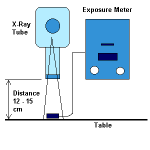
- Secure the dosemeter to a flat surface. Position the x-ray tube centred to the dosemeter with the cone tip at least 12 cm away from the dosemeter to eliminate backscatter. (See Figure 10 - 4).
- Select exposure factors which will give a reading of at least 100 mR at the dosemeter. These factors and the distance must remain constant throughout the test.
- Make one exposure without filters and record the dosemeter reading. This is the zero reading.
- Tape 2.0 mm aluminum to the cone tip and make an exposure. Record the results. Compare this to the zero reading.
- Continue adding (or taking away) aluminum to the beam until the measured radiation to the dosemeter has been reduced by one-half of its reading at zero (step 3).
- Remove the aluminum and make another exposure to ensure that the unit has maintained a constant output. The output should be the same as the original exposure. Allow up to 10% difference. If error is greater, ensure that the unit is reproducible and repeat.
- Determine the thickness of aluminum which was required to reduce the exposure to one-half of the original value. This is the half-value layer.
- Compare the half-value layer obtained with the half-value layer required for the measured kilovoltage used in the above Table 10-1.
Example
|
|
|
|
0.0 mm aluminum measured |
200 mR |
|
1.0 mm aluminum measured |
150 mR |
|
1.5 mm aluminum measured |
110 mR |
|
2.0 mm aluminum measured |
90 mR |
|
2.5 mm aluminum measured |
65 mR |
|
0.0 mm aluminum measured |
201 mR |
One half of the original intensity is 100 mR.
From the figures above, the amount of aluminum required to reduce the original value by one half is halfway between 1.5 and 2.0 mm. Therefore, the half-value layer is 1.75 mm. aluminum.
kVp Testing
Section 20 1(c) of the HARP Regulation states:
"Every dental x-ray machine and every chiropodic x-ray machine shall be so constructed that,
(c) for any selected setting of the peak x-ray tube potential, the actual peak kilovoltage corresponds to the selected value to within +/- 8 per cent."
With the use of a digital kVp meter, measure the kVp and ensure that it is within +/-8% accurate.
Timer Tests
Standard
Section 11 (1) of the HARP Regulation states:
"Every diagnostic x-ray machine and every fluoroscopic x-ray machine shall be so constructed that the timing device on the machine terminates an irradiation on completion
of'
(a) a preset time interval;
(b) a preset product of current and time; or
(c) a preset number of pulses,
Except where the x-ray machine is equipped with an automatic exposure control device."
Section 11 (3) of the HARP Regulation states:
"Every timing device on a diagnostic x-ray machine and fluoroscopic x-ray machine shall be so constructed that it,
(a) resets automatically to its original position or to ZERO on termination of an irradiation; and
(b) prevents and irradiation from occurring at the ZERO or OFF position."
Section 13 (2c-d) of the HARP Regulation states:
"Every diagnostic x-ray machine shall be so constructed that,
(c) the timer on the x-ray machine may be set to control irradiations as short as 1/30 second or five milliampere-seconds, whichever is greater;
(d) at each setting over the normal range of use, the timer on the x-ray machine is accurate to within +/-lO per cent."
Section 20 (1b) of the HARP Regulation states:
"(lb) Every dental x-ray machine and every chiropodic x-ray machine shall be so constructed that when the x-ray machine is operating in the fixed milliamperage mode, the timer is, at each setting, accurate to within 1/30 second (two cycles) or l0 per cent of the set value."
This standard does not take into account the pre-heat phase of dental x-ray machine exposure. Sensitive digital x-ray timers measure this preheat even though very little radiation is being produced. To compensate for this anomaly, timer linearity is compared as opposed to the actual accuracy.
Test for:
Accuracy/linearity
No exposure at zero or at off position
Deadman
Automatic reset
Minimum exposure
Equipment
Digital x-ray timer, or
Pulse counter
Procedures:
Testing Timer Accuracy and/or Linearity
Place the timer on a flat surface using the same orientation as previously described for PEE measurement.
Select the exposure normally used for bitewings and expose and record time measured.
Double the time used in step 2, expose and record.
Select an exposure time of one-half that used for bitewings, expose and record.
Evaluate as follows:
Ensure that time measured is within 10% of that selected or ensure that the timer is linear.
For timers with anatomical selections, patient size selections and film type selections, an assessment should be made as to whether the patient size selector and the film type are working properly.
Testing for Exposure at Zero
Ensure the timer is inoperative at zero or off position.
The x-ray machine must not produce an exposure when set at the zero or off position. If an exposure is measured, the machine must not be used again until the problem is corrected.
- Make an exposure with the time set at the zero or off position (if applicable).
If an exposure occurs, then the unit must not be used again until the problem is corrected.
Testing Deadman
Ensure that the timer has a deadman feature. That is a switch that requires continuous pressure by the operator to produce x-rays.
After making one full exposure at the maximum time setting (within the normal range of use), we recommend 1.0 see., take a second exposure at 1.0 sec. however this time make this one a partial exposure, that is release the exposure switch before it has reached 1.0 sec.(deadman).
Ensure that the second exposure time measured is much less than the first.
Note:
This test is difficult to do, therefore, we suggest that it not be done with less
than one second exposure time.
If there is no deadman feature, the unit must not be used again until the problem is corrected.
Testing for Timer Resets or Zeros on Completion of Exposure
The timer must automatically reset itself to its original position or to zero without radiation after any exposure. If not, it must not be used again until the problem is corrected.
Testing for Minimum Exposure Time
The x-ray machine must be capable to produce exposure time as low as a 1/30 second or 5 mAs, whichever is greater. (Not applicable to Panoramic machines.)
Select the shortest exposure time and ensure that it is within the standard listed above. Evaluate as follows:
If any of the following does not meet standard, the x-ray machine must bc taken out of service until such time that is has been serviced and the test is repeated to confirm proper functions.
Review of acceptable timer functions:
Minimum Exposure Time
The x-ray machine must be able to be set at 1/30 second or 5 mAs. (Not applicable to panoramic.)
Timer Inoperative at Zero or Off Position
The x-ray machine must not produce an exposure when the timer is set at the zero or off position. If an exposure is measured, the machine must be immediately taken off-line and serviced.
Timer Accuracy
Measured time must be accurate to within +/- 1/30 second or +/-10 per cent.
Timer Resets or Zeros on Completion of Exposure
The timer must reset or zero itself after an incomplete or complete exposure without radiation. If the machine does not reset or zero, it must be immediately taken off-line and serviced.
Reproducibility
Ensure timer is reproducible within a coefficient of variation within 0.08
Deadman
Radiation stops when the operator releases the exposure switch.
Panoramic
Collimation and Beam Alignment
Standard
For panoramic x-ray machines, Section 22 of the HARP Regulation states:
"Every panoramic x-ray machine shall be equipped with a beam limiting device that limits the useful beam at the image receptor to a size not more than 2% of the source-to-image receptor distance at each dimension of the scanning slit."
Equipment
Four unexposed intra-oral films
Masking tape
Straight pin
Procedure
Method 1
Figure 10-5 Dental Film Placement at Slit
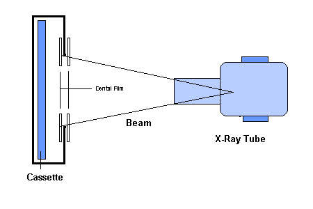
- Tape two film packets to the top of the scanning slit, with one film in from of the slit and the other film behind the slit. The identifying dot on the film should be in the upper right comer. (See Figure 10 - 5)
- Repeat step one with two more films at the bottom of the slit.
- Using the pin, pierce through the upper and lower film packets at the end of the scanning slit so that the films may be aligned after development.
- Make an exposure using exposure factors normally used for an average-sized adult.
- Process films.
- Evaluate the results. (See Figure 10 - 6.) The dental film in from of the slit will generally indicate a beam somewhat larger than the beam behind the slits.
- If the beam is larger than the slit or misaligned, it must be corrected.
FIGURE 10-6: Samples of Normal and Abnormal Collimation
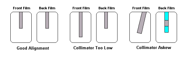
Method 2
On some types of panoramic x-ray machines, it is impossible to tape film behind the collimator slit. Method 2 specifies the test procedure for machines where this restriction applies.
Figure 10-7 Preparation of Film
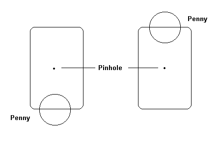
Figure 10-8 Placement of Film
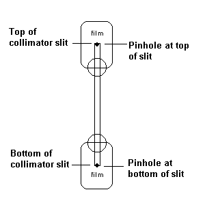
- Tape a penny to the lower third of each intra-oral dental film. (See Figure 10 - 7.) Using a pin, make a hole in one of the films and two holes in the other.
- Position the film over the top and bottom of the slit as shown in (Figure 10 - 8).
- Make an exposure using exposure factors normally used for an average-sized male.
- Process the films.
- Examine the resultant radiograph. Both films should produce an image of the coin superimposed over the beam. The image should be centred over the beam and the upper and lower edges of the beam should also appear on the film. If the image of the beam is not centred in reference to the penny or perpendicular to it, or if the upper or lower edges of the beam exceed the dimensions of the scanning slit, the collimation should be adjusted. (See Figure 10 - 9.)
Figure 10-9: Examples of normal and abnormal collimator alignment
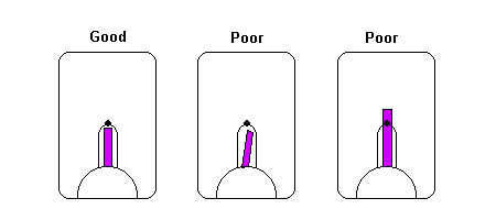
Cephalometric
Patient Entrance Exposure
Test for:
PEE - Lateral View, Average Size Adult
Half-value Layer
Collimation
Timer Accuracy
kVp Accuracy
Equipment
Radiation Dosemeter
Masking Tape
Procedure
Figure 10-10 Setup for Cephalometric X-ray machine
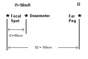
- Set up the cephalometric x-ray machine as it would normally be used. For an average sized adult, the ear pegs should be 15 cm apart. 20
20 If special filters are used for the face, remove them so that they do not interfere with the PEE measurement.
- Set the exposure factors for a patient measuring 15 cm.
- Secure the dosemeter detector to the ear peg nearest the x-ray tube. Ensure that the dosemeter is in the x-ray field, aligned to the tube.
- Make three exposures and record the results. Ensure that the unit is reproducible
- Average the three exposures and record the PEE.
Note:
Occasionally the intensity of the x-ray beam may not be sufficient to trigger the dosemeter. If this is the case, move the detector closer to the source - take care that the detector chamber remains flooded (entirely exposed to radiation) and calculate the PEE using the inverse square law.
(7) Inverse Square Law

See Figure 10-10 for setup.
Using the numbers provided in the setup, the PEE is 12.5 mR.
Dose at the ear peg = (50 cm x 50 cm x 50 mR)/(100 cm x 100 cm)
Collimation and Beam Alignment
Standard
Section 23 of the HARP Regulation states:
"Every cephalometric x-ray machine shall be equipped with a beam limiting device that limits the size of the useful beam to maximum linear dimensions of thirty-one centimetres by thirty-eight centimetres at the plane of the image receptor. "
Equipment
Four intra-oral films
31 cmx 38 cm piece of cardboard
Masking tape
One loaded cassette or film holder
Procedure
Method 1
Examine a recent cephalometric radiograph. If collimation can be seen on all four sides, measure the dimensions of the exposed area to determine if the field is within limits. If it meets standards, no further testing necessary.
Method 2
Figure 10-11: Placement of films for cephalometric collimation test
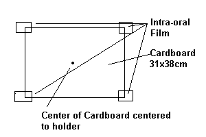
If collimation cannot be seen on all four sides of the radiograph, or if the collimator is adjustable, then the following test must be done.
- Tape the intra-oral films to the corners of the cardboard as shown in Figure 10 - 10.
- Place the cardboard in from of the film holder and align the centre of cardboard to the central x-ray.
- Expose the film using normal factors.
- Remove and process the intra-oral films.
- Evaluate the films. The area of film that was in contact with the cardboard should be the only area of the film exposed. Most modern collimators collimate less than this films will be unexposed (sic).
Method 3
Secure the cassette to the end of the collimator.
Expose the cassette using normal factors and develop the film.
The x-ray field size at the image receptor can be determined mathematically using the ratio of similar triangles. Measure the distance from the focal spot to radiograph used in test. Measure the distance to film cassette holder that is normally used at the facility. Measure the width and length on the exposed film used for test above. See Figure 10 - 12:
FIGURE 10 - 12 Measuring Collimation
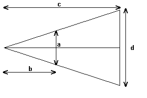
(8) Ratio of Similar Triangles

a--size of exposed area on radiograph
b--distance focal spot to film
c--distance focal spot to image receptor as used by facility(cassette holder)
d--size of radiation field at image receptor
Evaluate as follows:
The size of the calculated x-ray field must be within or less than the size of film used.
Tempero-Mandibular Joint (TMJ)
Introduction
The HARP Act does not present standards for TMJ attachments to intra-oral dental x-ray machines. However, the X-Ray Inspection Service has developed some recommendations for the testing of this type of machine.
Suggested Tests
Patient Entrance Exposure
Collimation
Tube - Film Alignment
Cassette holder
Note: A proper TMJ holder must be used to carry out the exam.
Patient Entrance Exposure
Patient Entrance Exposure is measured at the location where the patient's head would be nearest the x-ray tube at approximately 18 cm from the film. The measurement is based upon the lateral skull radiographic projection thickness of 15 cm. Select kVp, mA and time used for TMJ exam.
The exposure should not exceed 200 mR. If it does, the following factors should be reviewed: inadequate film/screen combination, poor processing, poor screen efficiency, etc.
Collimation
Ensure that the x-ray field is to the size of film used. If four to six exposures are taken on one film, ensure that the x-ray field collimating device is properly aligned such that overlap is possible.
Method 1
Examine a recent TMJ radiograph. If collimation can be seen on all four sides, measure the dimensions of the exposed area to determine if the field is within limits. If it meets standards, no further testing necessary.
Method 2
If collimation cannot be seen on all four sides of the radiograph, or if the collimator is adjustable, then the following test must be done.
- Cut a piece of cardboard to the size of film cassette used for TMJ.
- Tape intra-oral films to the corners of the cardboard such that they overhang the edges by 2.5 cm. Tape a penny on the x-ray film or punch a pinhole in the film to identify the outer comers of the cardboard (which represents the cassette size).
- Place the cardboard in front of the TMJ film holder and align the centre of cardboard to the central x-ray.
- Expose the film using normal factors.
- Remove and process the intra-oral films.
Evaluate as follows:
Ensure that the x-ray field is within the size of the x-ray film used. No x-ray field should be present beyond the penny or pin hole. If the x-ray field is beyond the size of the cassette, have the collimation corrected.
Constructing a Dental Step Wedge
A step wedge should be purchased from a dental supplier or a company which sells quality assurance equipment. A home-made step wedge cannot be standardized and false information could result. A home-made step wedge may be considered a temporary solution until a proper step-wedge can be purchased.
Equipment
Step wedge
Intra-oral films
Extracted tooth (optional)
Procedure
Cut one fifth of the length of lead backing from one of the pieces of film.
Cut two fifths off one of the other pieces of lead backing.
Cut three fifths off the third piece of lead backing.
Cut four fifths off the fourth piece of lead backing.
Stack the five pieces of lead backing in such a manner as to create even steps. (See Figures 10 - 12 and 10 - 13.)
Staple the five layers together at their thickest part.
Place the extracted tooth beside the step wedge. This step is optional but gives additional information, such as the contrast difference between enamel and dentine.
Figure 10-13a Top View
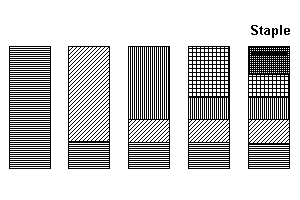
Figure 10-13 Side View

Photographic Quality Assurance
Week of :
|
|
Day 1 |
Day 2 |
Day 3 |
Day 4 |
Day 5 |
Day 6 |
Total |
|
Technical Tests |
|
|
|
|
|
|
|
|
|
|
|
|
|
|
|
|
|
|
|
|
|
|
|
|
|
- Solution Topped up or replaced
|
|
|
|
|
|
|
|
|
|
|
|
|
|
|
|
|
|
Film Tests |
|
|
|
|
|
|
|
|
|
|
|
|
|
|
|
|
|
|
|
|
|
|
|
|
|
|
Totals |
|
|
|
|
|
|
|


